Getting My Wedge Barriers To Work
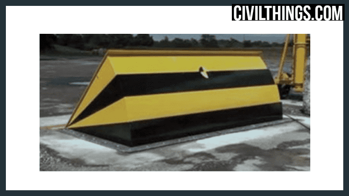
In the detailed embodiment, the obstacle 10 includes a wedge plate 16, which consists of a section that is significantly identical with the surface 12 when the barrier 10 is in the withdrawed setting. In other words, automobiles or individuals may pass over the barrier 10 when the barrier 10 is in the pulled back setting and experience small elevation loved one to the surface area 12 while on the barrier 10. As the obstacle 10 is placed to the surface 12 of the structure 14, collection of particles and other material beneath the barrier might be reduced, and components of the bather 10 might not be exposed to below grade settings.
About Wedge Barriers
g., spring assistance 65 )might be repaired to completion of the spring pole 58 to enable compression of the springs 60. As the springtimes 60 are pressed in between the springtime sustains 62, the springtime setting up 54 generates a force acting upon the webcam paired to the spring rod 58 in a direction 66. For instance, the staying force related to
the camera to release the wedge plate 16 might be provided by an electromechanical actuator 84 or other actuator. Because of this, the springtime assembly 54 and the actuator 84(e. g., electromechanical actuator)may run together to convert the camera and raise the wedge plate 16.
As pointed out over, the spring setting up 54 applies a constant force on the webcam, while the electromechanical actuator may be regulated to apply a variable pressure on the cam, thus enabling the training and lowering( i. e., releasing and pulling back )of the wedge plate 16. In certain embodiments, the consistent pressure used by the spring setting up 54 might be adjustable. g., electromechanical actuator) is impaired. As will be appreciated, the springtime assembly 54 might be covered and safeguarded from debris or other components by a cover plate(e. g., cover plate 68 displayed in FIG. 4) that might be substantially flush with the raised surface area 38 of the structure 14. As pointed out above, in the released placement, the wedge plate 16 offers to block gain access to or travel past the obstacle you can try this out 10. For example, the obstacle 10(e. g., the wedge plate 16 )might block pedestrians or vehicles from accessing a building or path. As reviewed above, the obstacle 10 is connected to the support 30 secured within the structure 14,

front braces 71. Consequently, the link settings up 72 may pivot and rotate to enable the collapse and expansion of the link settings up 72 throughout retraction and implementation of the bather 10. The linkage settings up 72 reason activity of the wedge plate 16 to be limited. If a car is traveling in the direction of the released wedge plate 16(e. For example, in one circumstance, the security legs 86 might be prolonged duringmaintenance of the barrier 10. When the security legs 86 are released, the safety legs 86 support the weight of the wedge plate 16 versus the surface 12. Therefore, the training system 50 may be shut down, serviced, removed, changed, and so forth. FIG. 5 is partial viewpoint sight of an embodiment of the surface-mounted wedge-style obstacle 10, showing the web cam 80 and the webcam surface areas 82 of the training system 50. Especially, two webcam surface areas 82, which are referred to as reduced web cam surface areas 83, are positioned listed below the cam 80. The lower webcam surface areas 83 may be taken care of to the surface area 12 (e. As an example, the reduced cam surfaces 83 and the installing plate 85 might form a single piece that is protected to the support 30 by screws or other mechanical fasteners. Additionally, two cam surfaces 82, which are referred to as top camera surface areas 87, are placed over the web cam 80 and paired to (e. In other embodiments, stepping in layers or plates might be placed between the surface 12 and the lower cam surfaces 83 and/or the wedge plate try here 16 and the upper webcam surface areas 87 As stated above, the web cam
80 converts along the webcam surface areas 82 when the wedge plate 16 is lifted from the withdrawed placement to the released position. In addition, as discussed above, the spring assembly 54 (see FIG. 3 )might give a pressure acting upon the camera 80 in the instructions 102 through spring pole 58, which may reduce the force the electromechanical actuator 84 is called for to apply to the webcam 80 in order to actuate and lift the wedge plate 16. 1 )to the deployed position(see FIG. 4). As revealed, the cam 80 includes track wheels 104(e. g., rollers), which call and equate along the web cam surface areas 82 throughout operation.